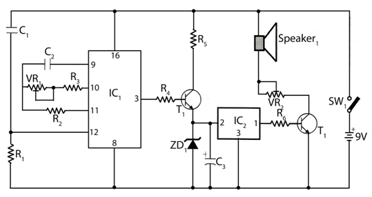
The timer with Musical Alarm use famous CMOS oscillator/divider
IC (IC1 ). Although this circuit operates in 9V its standby current
drain is very low. The time delay of timer circuit can be adjusted by
adjusting the preset VR1. The base of npn transistor T1 is connected to
pin 3 of IC1 through resistor R4 and its emitter terminal is connected
with pin 2 of melody generator IC (IC2) in order to provide positive
supply when adjusted time delay is over.
Timer with Musical Alarm Circuit Diagram
Timer with Musical Alarm Circuit Diagram
Here the zener
diode ZD1 is used as regulator which reduce power supply to required for
operation of IC2 i.e. 3.3V. Lastly for music output the output from pin
1 of IC2 is fed to loud speaker via driver transistor and its volume is
controlled by preset VR2. For starting the timer power is supplied by
pressing switch SW1.
Parts list
Resistor (all ¼-watt, ±5%)
R1 = 1.2 MΩ
R2 = 2.2 MΩ
R3 = 56 KΩ
R4, R5, R6 = 1 KΩ
VR1 = 1 MΩ
VR2 = 1 KΩ
Capacitors
C1 = 0.01 µF
C2 = 0.22 µF
C3 = 1 µF/25V
Semiconductors
IC1 = CD4060 (CMOS oscillator /divider IC)
IC2 = UM66 (melody generator)
T1, T2 = BC547
Miscellaneous
SW1 = on/off switch
9V battery
LS1 = 8Ω, 0.5W speaker
If You Enjoyed This Project My Pleasure Take 5 Seconds To Share It.


0 comments:
Post a Comment