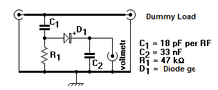
This is the RF Probe for Multimeter Circuit DiagramTo measure the RF voltage in a circuit to convert the signal unless they RF voltmeter. This conversion may be done with a very simple circuit, called a point or RF probe. A tip for RF Multimeter has to be made in a metal box with two connectors, one that receives the RF signal and another that goes to the multimeter.
In the case of this circuit the signal passes through two connectors between them and the RF signal is picked up.This signal passes through a 18 pF capacitor, a diode germanium, a resistor of 47 kOhm, and a bypass capacitor 33 nF. The anode of the diode is connected to the positive lead of the voltmeter and the other to ground.
RF Probe for Multimeter Circuit Diagram


0 comments:
Post a Comment