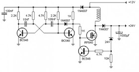
DC Converter - DC 12V to 24V Circuit Diagram. A voltage converter is very useful, if it raises the voltage from 12v to 24v. Can be used to power low power equipment and even a battery charger Notebook. It works with a two-transistor oscillator, type astable which drives a power transistor controlled by a Zener diode. Thus is achieved with a good efficiency and stabilize the output voltage of 24V.
The coil should be wound on a ferrite core in the form of 1 cm and consists of 100 turns of wire of 1 mm section.
The coil should be wound on a ferrite core in the form of 1 cm and consists of 100 turns of wire of 1 mm section.
DC Converter - DC 12V to 24V Circuit Diagram


0 comments:
Post a Comment