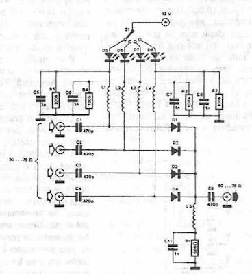
This Selector Antennas using PIN Diodes Circuit Diagram selector antennas uses PIN diodes, was designed using common components and is very useful when used various external antennas, this antenna selector uses PIN diodes that eliminate disadvantages of mechanical switches especially at high frequency.
Capacitors C1 to C4 and C9 are used to prevent the input and output circuit DC. Shock L1 to L5 prevent leakage of HF signal.Shock L1 to L5 can be wound on a ferrite core, using enameled copper wire of 0.3 mm in diameter, two rounds will suffice for entries for VHF and UHF 5 (1 mH is required for VHF and UHF about 5 uH). The circuit was designed for antenna input impedance of 50 or 75 ohms.
Selector Antennas using PIN Diodes Circuit Diagram


0 comments:
Post a Comment