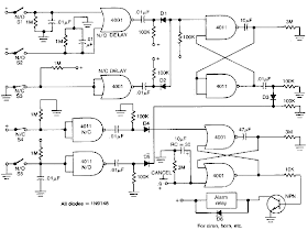
This is the House security monitor system Circuit Diagram. This circuit provides normally open (NO) and normally closed (NC) contacts SI, S2, and S3 to turn on the alarm after a 30 second delay. S4 and S5 operate instantly The CANCEL switch resets the alarm.
Home »
Alarm and Security
» House security monitor system Circuit Diagram


0 comments:
Post a Comment